Active Vibration Isolation countermeasure to LCD panel inspection tool
- Category
-

-
- Type of equipment/device
-
- Air conditioning/Sanitary equipment
- Electrical equipment
- Buildings/Structures
- Precision equipment
- Vibration-sensitive equipment
-
- Vibration obstacle phenomena
-
- Vibration
- Noise
- Magnetic fields
-
- Type of usage environment
-
- Living environments
- Office buildings
- General facilities
- Factories
- Research facilities
-
- Building type
-
- Hotels/Accommodations
- Hospitals/Welfare facilities
- Office/Meeting rooms
- Store/Commercial buildings
- University Labs/Schools
- Condominiums/Houses
- Plants/Factories
-
- Background of countermeasure
- When Tokkyokiki measured floor vibration environment of installation place for the large size LCD panel inspection tool (dimension measurement), it was found that low frequency vibration spectrum exceeded the specified floor vibration limit of the tool. The weight of large size LCD panel inspection tool is usually several ten tons, center of gravity (COG) of the tool constantly shifts due to the large moving part inside the tool, and moving speed of the moving part is rather fast. For such case, passive type vibration isolation countermeasure may face issues such as posture maintenance difficulty and/or longer settling time (poor throughput) against COG shift. After careful examination of all the factors, Tokkyokiki implemented countermeasures by the active vibration isolation (AVI) system, and it’s working properly now.

Floor vibration environment of tool installation location
Manufacturing of LCD panel is carried out in the clean room, and vibration environment is poor in general. For this example’s installation location, the vibration on the raised access floor as well as the solid substrate (concrete slab) exceeded the specified vibration limit of the tool.
Natural frequency of installation floor was approximately 5Hz and exceeded the specified limit for the vertical direction. To make the matter worse, since it was upper floor of the building, horizontal direction exceeded the specified limit approximately at 1.5Hz which was horizontal natural frequency of the building itself.
For such case, it was predicted that the vibration became larger due to the disturbance by the wind and/or ground vibration caused by surrounding traffic and/or several vibration excitation sources inside the building. Therefore, Tokkyokiki decided to conduct sufficient countermeasures taking all factors into account.
In addition, since the target LCD panel inspection tool had large internal moving part, COG shift constantly occurred. The tool may have been be tilted significantly when it was sustained by elastic body and the yield would be deteriorated, so such countermeasures were also considered. The vibration measurement data (Tripartite graph) before the countermeasure is shown from Fig 1 to Fig 3.
-
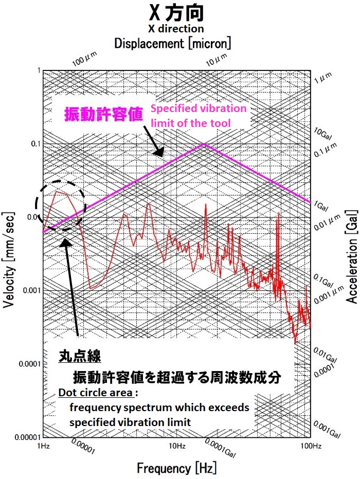
Fig 1 : Floor vibration (Tripartite graph) of the installation location. X direction
-
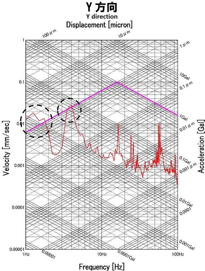
Fig 2 : Floor vibration (Tripartite graph) of the installation location. Y direction
-
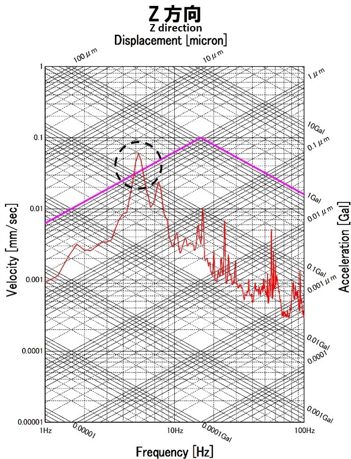
Fig 3 : Floor vibration (Tripartite graph) of the installation location. Z direction
Required performance to the vibration isolation system
According to Fig 1 to Fig 3, the frequency range which needed vibration isolation was rather low from 1Hz to 6Hz and it was amplification area for passive vibration isolation system, so the active vibration isolation (AVI) system was adopted.
Also, large mass stage moves X/Y direction, prompt swing settlement was required to improve the throughput.
Therefore, not only vibration isolation performance but also vibration control performance by the active control was highly expected. Fig 4 to Fig 5 shows vibration displacement measurement result on the floating table of Active Vibration Isolation (AVI) system. It shows that displacement fluctuation by COG shift and inertial force was promptly settled.
-
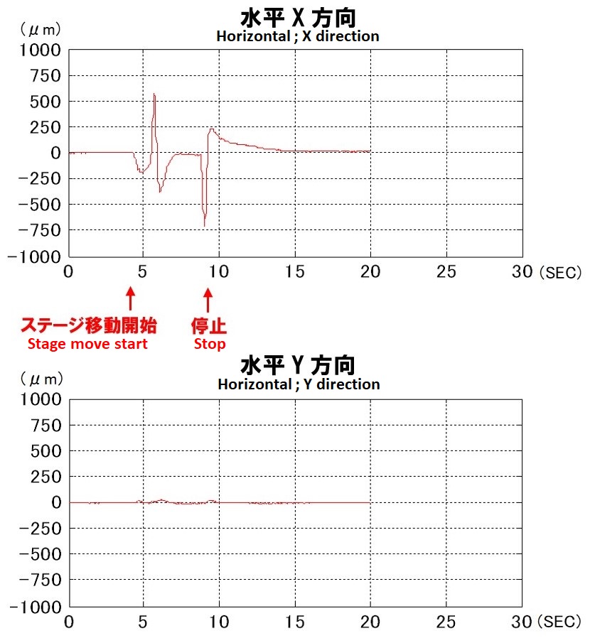
Fig.4:Floating table displacement when the stage moves x direction.(Horizontal direction)
-
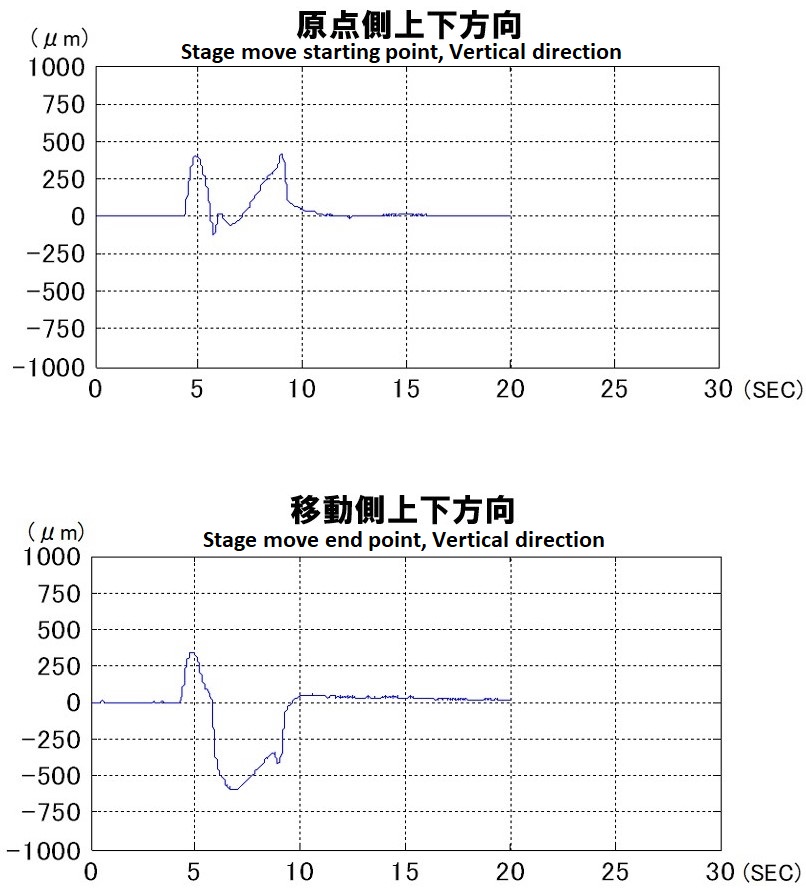
Fig.5:Floating table displacement when the stage moves x direction.(Verticall direction)
Vibration measurement result after active vibration isolation countermeasure
The vibration measurement data on the AVI system (blue line) is shown Fig 6 to Fig 8. If compared with floor vibration data, it does not have amplification range, and floor vibration is isolated from low frequency. As a result, target tool’s specified vibration limit was cleared, and created excellent vibration environment for all the frequency range.
-
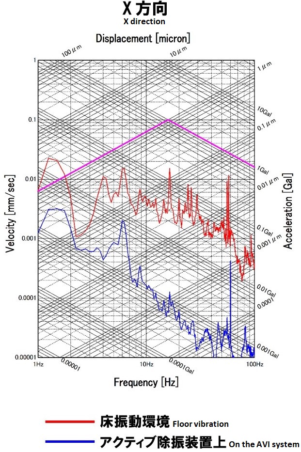
Fig.6: Active vibration countermeasure effect (X direction, Active ON/OFF)
-
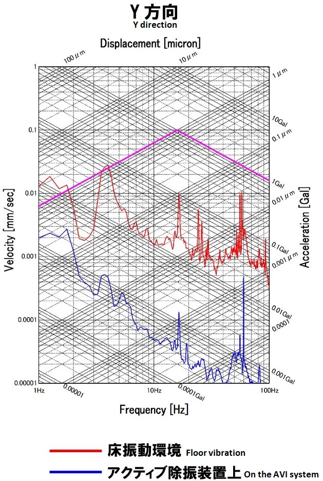
Fig.7: Active vibration countermeasure effect (Y direction, Active ON/OFF)
-
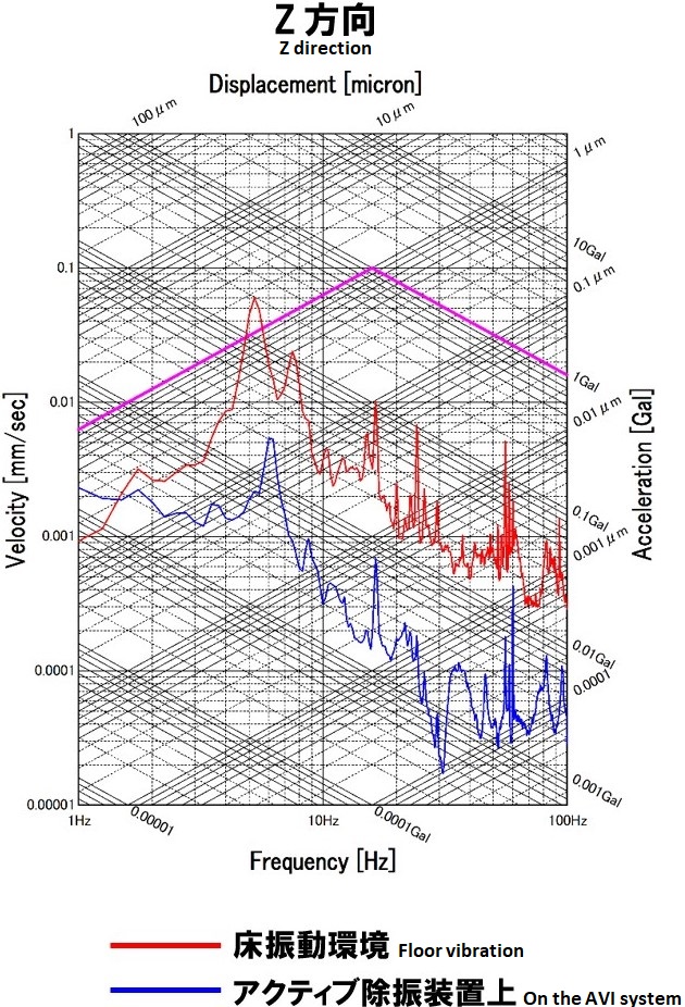
Fig.8: Active vibration countermeasure effect (Z direction, Active ON/OFF)