Passive and Active Vibration Isolation countermeasure to precision equipment
- Category
-

-
- Type of equipment/device
-
- Air conditioning/Sanitary equipment
- Electrical equipment
- Buildings/Structures
- Precision equipment
- Vibration-sensitive equipment
-
- Vibration obstacle phenomena
-
- Vibration
- Noise
- Magnetic fields
-
- Type of usage environment
-
- Living environments
- Office buildings
- General facilities
- Factories
- Research facilities
-
- Building type
-
- Hotels/Accommodations
- Hospitals/Welfare facilities
- Office/Meeting rooms
- Store/Commercial buildings
- University Labs/Schools
- Condominiums/Houses
- Plants/Factories
-
- Performance Comparison between Passive and Active Vibration Isolation
- Quiet vibration environment is essential for microfabrication (and inspection, analysis) process which is represented by semiconductor industry. For this objective, floor vibration criteria (floor vibration limit of the tool) is generally specified for fabrication tools and/or inspection tools. If floor vibration exceeds specified limit of the tool, vibration isolation countermeasure is definitely needed for each equipment. In this example, we will introduce passive and active vibration isolation (pneumatic) system data actually measured in the factory and performance comparison between passive and active system.

Pneumatic (Air Spring) vibration isolation system, and passive and active vibration isolation method
For the vibration isolation countermeasure, target tool is sustained by the elastic body, and this elastic body mitigates the vibration transmission from floor to target tool (Fig1). The basic performance is determined by the type and characteristics of elastic body, and higher isolation performance is obtained by the softer material. If target tool is precision equipment, pneumatic (air spring) is usually used as elastic body.
The main reasons are listed below.
(1) Possible to design the natural frequency lower by adding auxiliary tank (= higher isolation performance).
(2) Countermeasure against unbalanced load is easier.
(3) Flexible level adjustment. (Individual level adjustment is possible for each support point.)
(4) Attenuation adjustment is possible by the orifice which is set in the air flow path.
Vibration isolation method using elastic body’s spring characteristics is called “passive vibration isolation”.
In addition, when active control components (feedback and feedforward accelerometer, position control displacement sensor, actuator, controller) are added, it is called “active vibration isolation”.
In case of passive vibration isolation system, following disadvantages exist (Fig2).
(1) Since vibration amplification area definitely exists around the natural frequency, the vibration on the passive system is larger than that of floor for such area.
(2) Stability against posture maintenance is bad. (When direct disturbance is applied like stage move, displacement response is larger and swing settling time is longer.)
In case of active vibration isolation system, such disadvantages are improved.
(1) Vibration amplification area around the natural frequency is eliminated, and floor vibration is attenuated even surrounding the natural frequency.
(2) A few micrometers accuracy’s position and posture control are possible.
Active vibration isolation (AVI) system is applied for high performance tools which require accurate posture control and higher throughput.
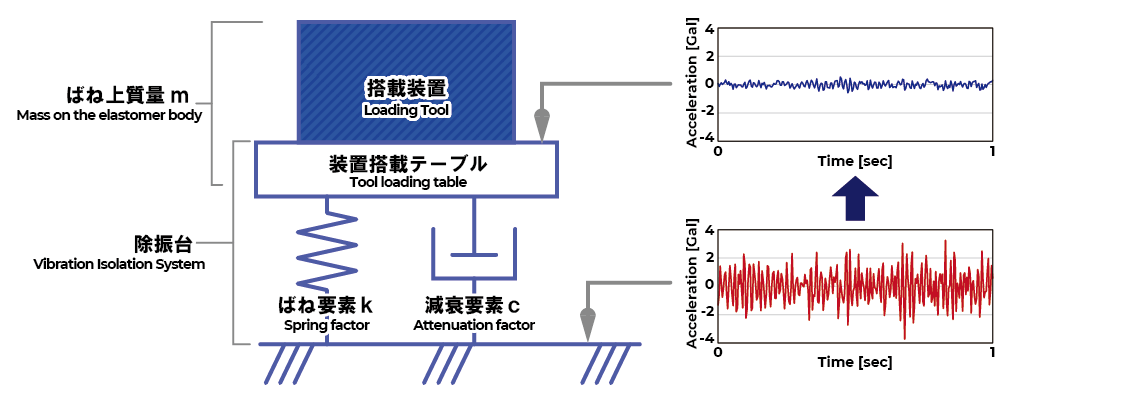
Fig 1: Vibration Isolation Model ( 1 DOF Model )
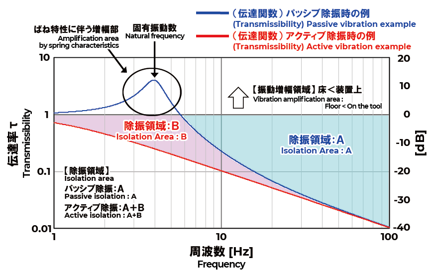
Fig2 : Passive/Active Vibration Isolation Performance ( Frequency Characteristics )
※ 1DOF Model Theory Characteristics
Actual measurement example (Overview of loading tool)
Overview of loading tool is summarized in table 1. Although tool weight and size are different between passive (FPD manufacturing equipment) and active (Electron microscope) example, the comparison is made for these two cases because floor vibration environment is similar. (※ Figure3, 4 : Refer to floor vibration data, both were installed in the middle floor.)
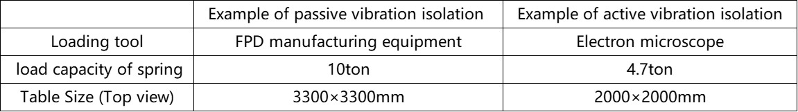
Table1: Overview of loading tool
Actual measurement result (Vibration isolation comparison by tripartite chart)
Vertical direction vibration data both floor (red line) and on the vibration isolation system (blue line) are shown in Fig 3 and Fig 4 respectively. Both passive (Fig3) and active (Fig4) example show good vibration isolation performance, however for the passive isolation example (left side), it is observed that vibration on the isolation system exceeds the floor one below 4Hz (circle portion). This part is corresponding to the amplification area by the air spring characteristics of passive isolation system. According to the VC (Vibration Criterion) evaluation, VC-F class is achieved by active vibration isolation system, on the other hand in case of passive vibration isolation system, it remains VC-C class due to the vibration amplification area.
-
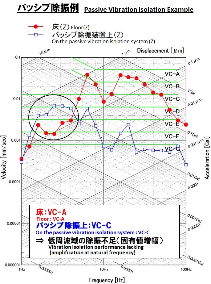
Fig3:Actual data [Tripartite、VC] Passive isolation
-
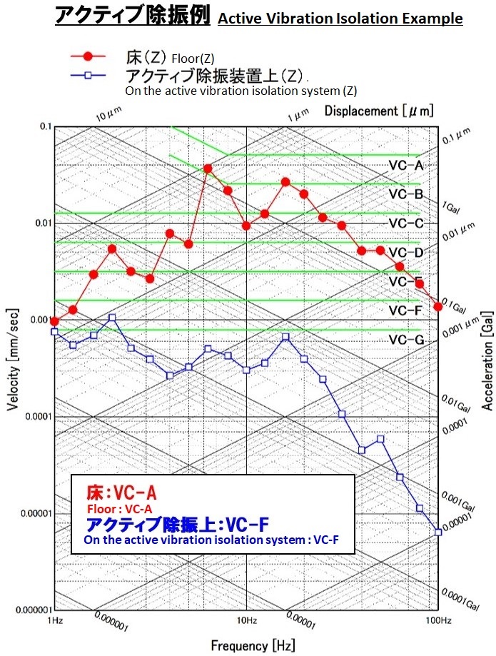
Fig4:Actual data [Tripartite、VC] Active isolation
Actual measurement result (Vibration isolation comparison by transmissibility curve)
Transmissibility characteristics curve between floor and on the vibration isolation system are shown in figure 5 and figure 6 respectively. Figure 5 and 6 shows vibration ratio (isolation performance) between floor and on the vibration isolation system. The 0dB means that floor and on the vibration isolation system’s vibration level is same (1:1), and if it’s below 0dB, the floor vibration is attenuated and isolated, and if it’s over 0dB, vibration on the isolation system is larger than that of the floor. Left side passive vibration isolation system (Fig5) has the peak at 2.5Hz (circle marked) which is natural frequency, and vibration is amplified around 2.5Hz. On the other hand, right side active vibration isolation system (Fig6), it does not have amplification area, and floor vibration is attenuated for all the frequency range under 100Hz.
-
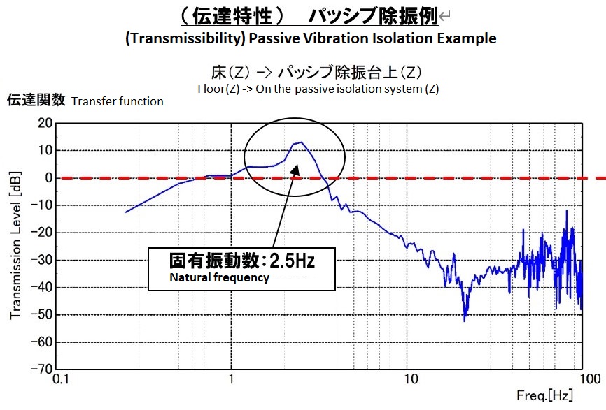
Fig 5:Actual data [Transmissibility between floor and on the passive isolator] Passive isolation
-
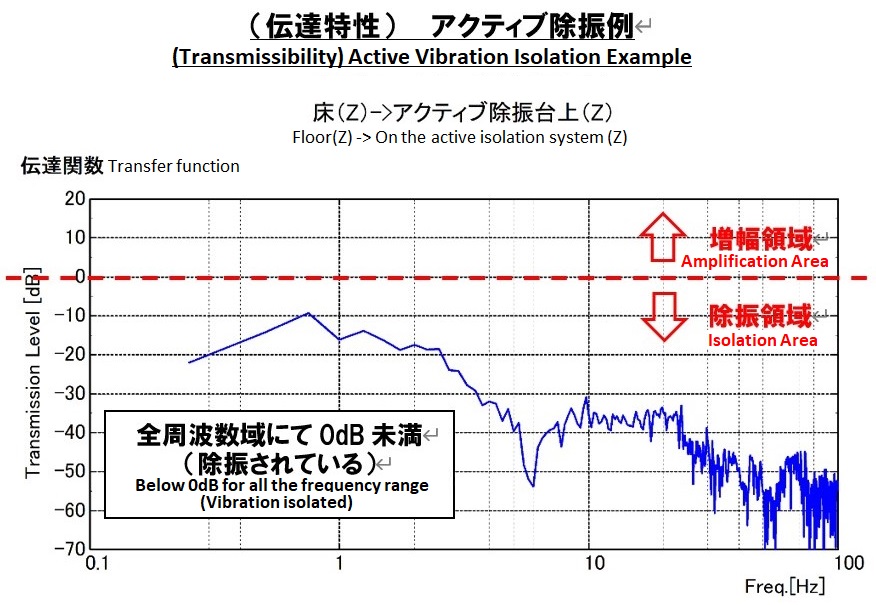
Fig 6:Actual data [Transmissibility between floor and on the active isolator] Active isolation